 |
|
||||
|
|
Frequently Asked
Questions
|
|
||||
 |
 |
|||||
 |
 |
|||||
 |
 |
|||||
|
||||||
The same principle is applied here, however the compressor remains attached to continuously optimize the air/fuel ratio during the full operation of the engines. To describe how this compressor apparatus would be incorporated into the design, first stretch out your right hand perpendicular to your body with each of four fingers extended that would be attached to the air intake of the four engines. Now rotate your arm in a clockwise rotation. A swivel interface would stand vertically as in this demonstration at you elbow. 2.
Block out external objects such as birds, wooded matter and other materials
that would otherwise be ingested into the engine damaging the engine
Also not shown are moveable "baffle plates within the water jacket"
that would be designed to move to and from the exhaust deflector as
required for the purpose of adjusting the amount of water inside the
water jacket to ensure that it leaves the water jacket at the desired
temperature.
The internal operational design (Click here) again shows
a large cross-section of the unit highlighting shows the interface for
the control system and the exhaust fan for the removal of exhaust gasses.
The exhaust gasses will be forced out of the chamber by a small pressure
head is inside the chamber, rotation of the aerodynamic shell of the
Reaction Force Rotation Unit, and the exhaust fan. The
load bearing parts of this system are identified at points (A) generator
a (B) rear housing. The load (weight of Reaction Force Rotation Unit)
will be suspended at point C, as indicated. (Click here)
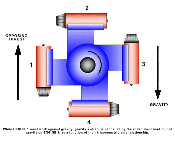
The operation of the system is as follows. The engines (connected
to the shaft which is in turn connected to a rotor of field) generates
thrust which causes the shaft and consequently the rotor of field
to rotate. (Click here)
As the engines generate thrust the provide rotation to the shaft-rotor
or field,the heat from their exhaust at 850 degrees to 1100 degrees
will be trapped in the exhaust deflector chamber and through conduction
transmitted to water in the surrounding water jacket and surrounding
the exhaust pipes leading from the exhaust deflector cover (see exhibit
5, enclosure A). One thousand (1,000) gallons of water per minute
at 210 degree can be derived from the heat of the engine-exhaust and
would be fed into the feed water of an existing steam utility plant
thus reducing the amount of energy that must be placed in the water
at the boiler interface.
The above represents a gross overview of the system as it is perceived
it would operate. More detail, date and analysis is presented throughout
this question and answer scenario to provide more insight into its
operation and capabilities.
The approach recommended for Reaction force Rotation Units, when the moment arms (leading from shaft to engine mounts are sized to operate at greater lengths (Click here) such as 20, 25, 30 or 35 feet is different from that employing the Aerodynamic Shell, as described above. But first a few points about the aerodynamic forces acting upon the
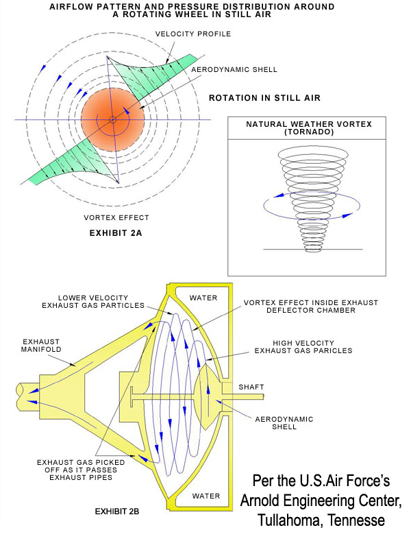
Aerodynamic Shell. Research and subsequent discussions with personnel
at the Arnold Engineering Research Center (A.E.D.C.) at Tullahoma,
Tennessee, where the Air Force's giant wind tunnels are located indicate
that THER IS NO DRAG ACTING UPON THE SHELL BECAUSE THERE IS NO HORIZONAL
VELOCITY DIRECTED TOWARD THE SHELL. Rather, the only retarding force
acting upon the wheel is "skin friction". This is very significant
because the drag equation requires that the velocity (speed at which
Aerodynamic Shell would rotate) term in the expression be squared.
which has a significant contributory effect to the amount of drag
that would act upon the shell as it would rotate.
Almost as significant is the affect of the "Area (A)" of
the Shell which forms a product of the velocity squared times A in
the drag equation.
The airflow pattern (Click here) illustrates what happen when a wheel rotates in still air. Particles
of air nearest to the surface of the wheel will adhere to its surface
due to viscosity and consequently rotate with it. The viscosity of
the air induces the surrounding air particles to follow the same path
as illustrated in that same exhibit which in effect created the rotary
motion of air around the wheel and the airstream velocity distribution.
as indicated. Such an air flow pattern is referred to in theoretical
aerodynamics as a "Vortex", which is , when compared to
drag is quite inconsequential.
But as stated above, area also comes into play as a strong contributor
to the amount of skin friction placed upon the rotating unit. To lessen
its (area-skin friction) contributory effect, it is necessary to stop
the motion of as many parts of the Rotating Unit as possible. Less
rotating area, thus less skin friction.
When longer moment arms are incorporated (Click here) all of the basic components of the Aerodynamic Shell are present,
but they all do not rotate. The outer half shell and inner half shell
do not rotate, whereas the rotating engine track does. The inner half
shell is fixed to the frontal inner section on the intake enclosure
while the outer half shell is disallowed motion, because it is no
longer a fixed part of the shaft. The shaft runs right through the
center of the outer half shell and rotates, but the lesser marginal
micro-diameter of the shaft with respect to the center pass through
point of the outer half shell will allow only the shaft to rotate;
not the outer half shell (although it would be attached to the chamber
in some way to assure its non-rotation).
|
||||||
